Well as I'm sure you have noticed by now, my backlog of posts has been used up. At this point I have a backlog of post titles, but I have yet to write the actual posts.
Wednesday, September 26, 2012
Monday, September 10, 2012
Bottleneck Slides
At the beginning of the summer, I decided to take up yet another hobby; luckily this time though, it is related to others I have, not too time consuming, and best of all, cheap: making guitar slides out of wine bottle necks. All it takes is a bottle scorer and wine bottles. I got my scorer at Hobby Lobby, but it is also available on Amazon.

 It's simple to use as long as you actually follow the directions. I actually did it a bit differently than the directions specified, but I still employed the same principles.
First, a little bit of science and clarification: whenever somebody talks about "cutting" glass, it is almost guaranteed that they are not actually cutting it. More often than not, it is actually controlled breaking: the way "cutting" glass works is by making a very fine score; the finer the score, the cleaner the "cut" or separation. When cutting a pane of glass for something like a window, a line is usually scribed along a straightedge, and the excess piece is carefully tapped until it cleanly breaks off. Bottlenecks are a little different though: since they are round, you obviously can't use a straightedge, and tapping the glass (though sometimes used) will almost always end with an at least somewhat jagged edge. What is needed then, is a way to score the glass, and make it want to crack, but in a more controlled manner.
Solving the problem of how to score the glass is fairly simple; all you need is a way to make a straight score on a pivot, which is the purpose of the bottle scorer.
 Actually getting the glass to break cleanly is a little trickier. Enter thermal shock: a way to break the glass without hitting it.
Basically, thermal shock will often cause stuff to crack due to uneven heating, and glass is especially susceptible to it. All that is needed is a source of high temperature, and a source of low temperature. These can range from candles to burning string soaked with lighter fluid to blowtorches to hot water from tap, likewise sticking stuff in a freezer to ice to cold water from the tap. I used the combination of a hot water kettle and cold water from the tap.
Now that I've explained the basic science behind it, here's the process:
 The first step is to line the scorer up perpendicular to the glass. Next I went around once with the scorer, going as lightly as possible while still making a score. The next step is to run it under boiling water and cold water over the score until it finally breaks. At this point, all it needs is some sanding of the edges to break the very sharp corners.
I think the rest of the bottle looks really cool, and I always feel like it has to be good for "something," but I haven't quite figured out what that something is yet.

Here is the finished product:

Monday, September 3, 2012
Bottleneck Slide Rack
Earlier this summer, I decided to start yet another hobby that I will get into in a later post, but for now I'll just leave this picture here:

The first step was getting the wood to the proper dimensions: I started with some pine that came from an old bed frame, and cut it to the dimensions, followed by planing it down to the proper thickness. After that, I needed to put the step in the block. I had originally planned on using a dado stack, but since we got our new SawStop, our old (but perfectly good) 6" dado stack won't work with it; instead, we need an 8" stack. Since spending around $200 on a new stack is not my top priority right now, I decided to use the router table outfitted with a straight bit. This worked perfectly fine, and was at least as easy. The next thing I needed to do was drill the holes for the shafts, and of course cut the shafts themselves.
To drill the holes, I chucked a forstner bit into my drill press and clamped a piece of MDF. To the table to act as a makeshift fence. I then marked out the center point of all of the holes, and started drilling. The fence was set so the drill press would drill with the center 3/4" in from the edge. And the depth stop to drill 1/4" deep. This was nice because all I had to do to drill the front and back was flip it around and adjust the depth stop. I ran into a little trouble after resetting for the lower level: since I didn't tighten the depth stop properly, I almost drilled straight through the board. Luckily, I realized what was happening in time to stop plunging. To fix it, I plugged the hole, and once the glue was dry, I re-drilled the hole.

The next step is extremely straightforward, all I had to do now was glue the shafts in place. All I did was put some glue in each hole, spread it around a little bit, and tap the shafts in. I didn't bother clamping it off two reasons: first off, it would be nearly impossible, and second, I just don't think it really needs it, since it isn't exactly going to be load bearing.

I plan to put a finish on it at some point, so you might see this rack return at some point, but it is ready for use.
What I Would Do Differently
The only thing I might have done differently was make an extra base to ease the clamping. I ran into some trouble with getting all the shafts straight, so a way to align them would have been helpful.Monday, August 27, 2012
Back at College!
Just a heads-up, I am indeed back at UNT. I moved in Move-in day was last Saturday, and though I think most if not all of my stuff is up here, I'm not exactly settled in and unpacked yet. Also, like last year, because I am back at UNT, the posts will certainly be slowing down. Luckily though, I have a backlog (albeit small) of posts that I need to format and add pictures to, but will be able to put those out on a somewhat regular basis. Who knows, maybe I will post a picture of my room once I'm done.
Monday, August 20, 2012
Fixing the Marantz
As I'm sure you are well aware of, I am going to college at UNT, and am staying in the dorms on campus. Now as great as my headphones are, I still like to listen to music through speakers every once in a while, and the speakers on my laptop don't cut it by a long shot. Because of this, I decided to bring my stereo up from home: the wonderful, magical, beautiful Marantz 2230.
It may be from the 70's, and it may weigh over 30 lbs, but it sounds fantastic! Anyways, it worked great for the first semester and about half of the second, but then I noticed that something weird was happening: the left channel was getting quieter and quieter. I could compensate by adjusting the balance for a while, but the white noise due to turning it up so loud to compensate for the imbalance finally got so unbearable that I had to use headphones plugged directly into the computer for the rest of the semester. Finally, a few weeks ago, my dad and I decided that it was time to fix it. The first step was isolating the problem: we began by narrowing it down to the preamps, which made sense, as there was one for each channel.
Luckily, we had not only the user manual (which actually came with a schematic), but also the service manual, which had schematics for each section as well as different values the components should read. We narrowed down the problem even more, figuring out which transistor made the left channel so much quieter than the right one. We started by replacing that transistor. No dice. We replaced a couple of capacitors, still nothing. Luckily, I remembered that we had another Marantz above the office more or less for parts, so I went up and brought it back down. We decided to just go ahead and replace the entire preamp, since by this time we were tired of troubleshooting. We cut the preamp loose, and proceeded to replace the preamp. My dad had been lamenting the length (or lack thereof) of the wire when trying to probe the preamp, so we decided to make sure there would be the perfect amount of wire to lay flat while working. After spending quite some time on that, we plugged the stereo back in and checked the signals. Same thing: the left channel was way quieter. We did find it fairly odd that both preamps had the same problem, but the parts unit had been above the office for so long that we had no idea what kind of condition it was in. We decided to cut the other preamp free from the parts unit to test, and this time use clip leads to connect them instead of soldering before testing. We hooked all the wires up, and it had the same problem! By this time, we began to suspect that maybe the left channel preamp wasn't the problem. We then decided to do what we should have done at the beginning: bring out the other Marantz 2230 we had (and knew worked), and compare the levels. As I'm sure you have figured out by now, the left channel was the correct volume, and the right channel was too loud! Once we finally figured that out, it was a relatively quick fix of replacing the right channel preamp. We got it put back together, and I now have a beautiful and fantastic sounding stereo to bring to college in a few weeks.
Edit: When I said we replaced the preamp, I was actually mistaken. What we actually replaced was the entire preamp and power module.
 |
| The legendary Marantz 2230. |
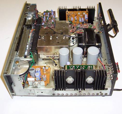 |
| Look at those big, beautiful preamps attached to the heatsinks! |
Luckily, we had not only the user manual (which actually came with a schematic), but also the service manual, which had schematics for each section as well as different values the components should read. We narrowed down the problem even more, figuring out which transistor made the left channel so much quieter than the right one. We started by replacing that transistor. No dice. We replaced a couple of capacitors, still nothing. Luckily, I remembered that we had another Marantz above the office more or less for parts, so I went up and brought it back down. We decided to just go ahead and replace the entire preamp, since by this time we were tired of troubleshooting. We cut the preamp loose, and proceeded to replace the preamp. My dad had been lamenting the length (or lack thereof) of the wire when trying to probe the preamp, so we decided to make sure there would be the perfect amount of wire to lay flat while working. After spending quite some time on that, we plugged the stereo back in and checked the signals. Same thing: the left channel was way quieter. We did find it fairly odd that both preamps had the same problem, but the parts unit had been above the office for so long that we had no idea what kind of condition it was in. We decided to cut the other preamp free from the parts unit to test, and this time use clip leads to connect them instead of soldering before testing. We hooked all the wires up, and it had the same problem! By this time, we began to suspect that maybe the left channel preamp wasn't the problem. We then decided to do what we should have done at the beginning: bring out the other Marantz 2230 we had (and knew worked), and compare the levels. As I'm sure you have figured out by now, the left channel was the correct volume, and the right channel was too loud! Once we finally figured that out, it was a relatively quick fix of replacing the right channel preamp. We got it put back together, and I now have a beautiful and fantastic sounding stereo to bring to college in a few weeks.
What I Would Do Differently
CLIP LEADS CLIP LEADS CLIP LEADS!!! Never again will I solder something like that again without first testing it with clip leads. I also would probably compare it with a known source if possible. Because it was important to compare known amplitudes, we used a function generator with the leads precariously clipped onto a headphone jack-to-stereo RCA cable. If I ever have to do something like this again, I definitely plan on making a BNC-to-stereo RCA cable; it would make the entire process much easier.Edit: When I said we replaced the preamp, I was actually mistaken. What we actually replaced was the entire preamp and power module.
Friday, August 17, 2012
Polycarbonate For the Control Panel
The thing I had alluded to in the last post was making a polycarbonate (Lexan) overlay for the control panel. This was worthwhile, if not necessary, for a number of reasons: First off, people are going to be touching the nice pretty white control panel with their grimy hands all the time, so you want to be able to clean it. If you only had paint, between the grimy hands and the cleaning because of the grimy hands, it would eventually wear through the paint. The other reason is similar: using an overlay allows you to put fewer coats of paint on, and I believe I have mentioned before as to how much I despise painting.
Now for the process of making the panel:
I started out by tracing out the shape of the panel, and cut it with plenty of room to spare. I then marked out where I was going to put holes for screws on both the panel and the overlay. When marking the screws, I put painters tape over approximately where I knew I would be drilling holes, then marked 1/2" in from each edge with my special 0.3mm mechanical pencil (everyone who knows me is disturbed by my love for them). The reason for the painters tape in case you were wondering is that it helps to keep marks off of the board, and also helps to avoid marring the surface from a misbehaving drill bit. After drilling the holes and countersinking, I peeled off the bottom plastic sheet, and fastened it to the board. After that, I used a flush trim bit and routed out each hole with my router table, using the hole in the panel as a guide. At this point, I was basically done; all I had to do was peel off the top sheet and I was good to go!
If I could, I would definitely mark the screws differently; once mounted, the panel bowed up between two screws, due to a mismeasurement. I would also like to do something different when fastening and routing the overlay. I got shavings of Lexan underneath the overlay and was afraid to do anything with them, because I didn't want to scratch anything with them. Next time, I would probably leave the bottom sheet on, fasten it, rout it, take it off, clear all the shavings, peel off the bottom sheet, then very carefully refasten it using the same holes. I would also not use it in a router table configuration; the router was full of pieces of Lexan, which was hard to get out. I would use a different bit, and use it in handheld configuration to let gravity take care of the stuff for the most part at least.
Now for the process of making the panel:
 |
| Cut and ready to mark. |
What I Would Do Differently
If I could, I would definitely mark the screws differently; once mounted, the panel bowed up between two screws, due to a mismeasurement. I would also like to do something different when fastening and routing the overlay. I got shavings of Lexan underneath the overlay and was afraid to do anything with them, because I didn't want to scratch anything with them. Next time, I would probably leave the bottom sheet on, fasten it, rout it, take it off, clear all the shavings, peel off the bottom sheet, then very carefully refasten it using the same holes. I would also not use it in a router table configuration; the router was full of pieces of Lexan, which was hard to get out. I would use a different bit, and use it in handheld configuration to let gravity take care of the stuff for the most part at least.
Tuesday, July 3, 2012
Getting it Upstairs
Before I left UNT, I managed to rope two friends into promising to help me get this cabinet upstairs (thanks Chris and Drew!).
It was of course a mad rush home on Friday after midterms, and I spend the first few days just relaxing a little bit and also brought the cabinet into the garage, letting us avoid airplane wings on the big move-in day. I also worked on something else that I will get to in the next post.
On Monday, Chris and Drew came over, and so it began. It was pretty much a nightmare trying to get it inside, as it barely fit through every doorway we had to go through. Once we got to the stairs though, is where it got really fun. I was at the top, and Chris and Drew were at the bottom; this was probably not the ideal arrangement in retrospect because Chris and I are close to the same height, and Drew is pretty darn short. Anyway, we managed to get it up to the landing, at which point, we all had the "What in the world are we doing?" moment. Once it was at the landing, we realized that we didn't have enough room to turn it to make the second corner, and nor was the stairway wide enough to take it up sideways. After deliberating for quite some time, we came up with the only possible solution (still haven't thought of a different one), and I wish so much that we had taken some pictures; it was surely a sight to behold! First, we laid they cabinet down on its back, and Drew crawled inside (told you he was small). There is a space in the back near the bottom if you remember, that's where Drew was. Keep in mind that the cabinet is 27.5" wide, and we probably had about 30" if that to work with; the clearances were approximately the same for the length as well. Once Drew was inside, we slowly and carefully proceeded to turn the cabinet upside down. Drew started by lifting it from the inside, since believe it or not, he had the most room at the moment. Once the bottom was a few feet off of the ground, Chris was able to get underneath, Drew got out, and they kept pushing it to upside down. I was on the other side, slowly moving it towards them so it wouldn't hit the wall. Now keep in mind that this cabinet weighs at least 200lbs, and is immensely bulky. Just go back to any picture of it if you need a refresher of the size of this. After this, we were able to maneuver the cabinet somewhat easily, if you discount the whole don't-let-the-top-heavy-200lb-arcade-machine-fall-over-and-destroy-something-and/or-itself factor. Anyways, we maneuvered the cabinet to the rail post, lifted the cabinet over the post and got it in line with the second flight of stairs. After managing to navigate the tight space to get on top to drag it up, we manged to get it up to the floor of my room.Getting it into the room was the easy bit, and and I slid the TV in, just to see kind of how it will look when it is done. Luckily, I did take a picture of that:
 I think it looks great even just like that.
It was of course a mad rush home on Friday after midterms, and I spend the first few days just relaxing a little bit and also brought the cabinet into the garage, letting us avoid airplane wings on the big move-in day. I also worked on something else that I will get to in the next post.
On Monday, Chris and Drew came over, and so it began. It was pretty much a nightmare trying to get it inside, as it barely fit through every doorway we had to go through. Once we got to the stairs though, is where it got really fun. I was at the top, and Chris and Drew were at the bottom; this was probably not the ideal arrangement in retrospect because Chris and I are close to the same height, and Drew is pretty darn short. Anyway, we managed to get it up to the landing, at which point, we all had the "What in the world are we doing?" moment. Once it was at the landing, we realized that we didn't have enough room to turn it to make the second corner, and nor was the stairway wide enough to take it up sideways. After deliberating for quite some time, we came up with the only possible solution (still haven't thought of a different one), and I wish so much that we had taken some pictures; it was surely a sight to behold! First, we laid they cabinet down on its back, and Drew crawled inside (told you he was small). There is a space in the back near the bottom if you remember, that's where Drew was. Keep in mind that the cabinet is 27.5" wide, and we probably had about 30" if that to work with; the clearances were approximately the same for the length as well. Once Drew was inside, we slowly and carefully proceeded to turn the cabinet upside down. Drew started by lifting it from the inside, since believe it or not, he had the most room at the moment. Once the bottom was a few feet off of the ground, Chris was able to get underneath, Drew got out, and they kept pushing it to upside down. I was on the other side, slowly moving it towards them so it wouldn't hit the wall. Now keep in mind that this cabinet weighs at least 200lbs, and is immensely bulky. Just go back to any picture of it if you need a refresher of the size of this. After this, we were able to maneuver the cabinet somewhat easily, if you discount the whole don't-let-the-top-heavy-200lb-arcade-machine-fall-over-and-destroy-something-and/or-itself factor. Anyways, we maneuvered the cabinet to the rail post, lifted the cabinet over the post and got it in line with the second flight of stairs. After managing to navigate the tight space to get on top to drag it up, we manged to get it up to the floor of my room.Getting it into the room was the easy bit, and and I slid the TV in, just to see kind of how it will look when it is done. Luckily, I did take a picture of that:

Sunday, July 1, 2012
Approximately Five Months Overdue
No, I'm not talking about library books...
Anyways, when I came home for spring break, which I believe was late March, I managed to get extremely far along in the project. I should have been posting multiple times throughout the break, but I didn't, so I will be catching you up in several installments.
Anyways, when I came home for spring break, which I believe was late March, I managed to get extremely far along in the project. I should have been posting multiple times throughout the break, but I didn't, so I will be catching you up in several installments.
Saturday, January 14, 2012

And the painting is done (again)!
I really hope so anyways! I put the last coat on the cabinet the other day, so now I just need the paint to cure. I also painted the control panel; I only had to put one more coat of paint on the top, because I decided to put a piece of polycarbonate (Lexan) on the top to protect it. I came to this decision because I wasn't sure how I wanted to not only make it easy to clean since it is white after all, but also make it durable enough to withstand the constant rubbing/touching that might make the paint wear through to the MDF. The problem I have been running into is that the only size big enough for the control panel is 36" x 48"! I can probably use the extra for the bezel for the TV, but it's pretty flexible, so I'm not sure how well that will work.
Sunday, January 1, 2012
MAME Cabinet Status Update
Last Friday, we started to clean out the shop to make room for a new tablesaw and get rid of all the sawdust so I could paint the MAME cabinet. We finally finished cleaning it yesterday, and I put the first coat of new paint on the cabinet today. A lot of the paint soaked in, but it shouldn't take too many more coats.
This time I am using an oil-based enamel for all of the coats, so it will be a lot tougher, but it takes 24 hours between coats. I need more paint anyway, so I will go to Home Depot to get more paint while it dries tomorrow, and add another coat at 2:00.
 |
| Look, it has paint! |
Subscribe to:
Posts (Atom)